Discover what a Programmable Logic Controller (PLC) is, how it works, its types, programming languages, and applications in manufacturing and industrial automation. Learn how PLCs integrate with modern manufacturing systems and ERP software.
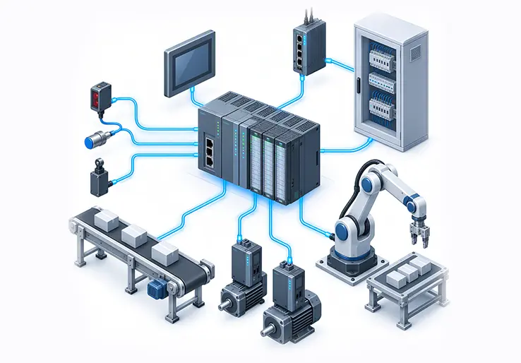
A programmable logic controller (PLC) is a specialized digital computer built to control machines and industrial processes through programmed logic. Unlike general-purpose PCs, a PLC is designed for industrial environments where a standard PC operating system can interrupt or delay execution, while a PLC is built for predictable control timing despite electrical noise, vibration, temperature swings, and dust that would destroy standard computing hardware. PLCs automate processes by receiving inputs from sensors and switches, evaluating a stored control program, and sending output signals to motors, valves, indicators, and other external devices.
Before PLCs existed, factories relied on relay logic systems: banks of electromagnetic relays wired together to perform sequencing and interlocking. Changing a production line meant physically rewiring relay panels, a process that consumed days or weeks. The programmable logic controller replaced those fixed relay systems with software-based control logic that engineers can modify, copy, and test without pulling a single wire. The term "PLC" was coined specifically to distinguish these industrial controllers from personal computers.
PLCs operate at the heart of modern control systems in manufacturing plants, packaging lines, food and beverage facilities, water treatment stations, power distribution networks, and building automation systems. Their defining characteristics make them the default choice for machine control at the device, cell, and line level.
The concept of a programmable controller emerged in the late 1960s when General Motors’ Hydramatic division needed a way to retool automotive assembly lines without rewiring relay panels every model year. PLCs were invented in 1964 for automobile manufacturing as a concept, and the first working unit, the Modicon 084, was built in 1969 under the leadership of Dick Morley, who is considered the father of the PLC. That first controller used about 1 to 4K words of magnetic core memory and executed ladder logic, a graphical programming style chosen because electricians already understood relay schematics.
Ladder logic’s adoption was deliberate. By mimicking the look of relay diagrams, PLC programming became accessible to the maintenance technicians who would troubleshoot these machines on the factory floor. Modicon created the Modbus protocol in the 1970s to allow controllers to communicate with each other, establishing one of the earliest industrial communication protocols. Around the same time, Allen-Bradley released the Bulletin 1774 PLC-1, and Siemens introduced its S-series controllers in Europe.
Key milestones in PLC evolution:
The trajectory moved from isolated, standalone controllers toward networked devices capable of sharing process data with supervisory control platforms and business applications.
A typical PLC system includes a central processing unit (CPU), memory, a power supply, input and output (I/O) modules, communication interfaces, and a programming device. In a modular PLC, these components slot into a shared rack or backplane, allowing engineers to add or swap I/O cards as a process changes. Compact PLCs integrate the CPU, a fixed set of I/O, and the power supply into a single housing, which suits standalone machines with stable I/O counts.
The signal flow through a PLC follows a clear path: field devices such as sensors and switches connect to input modules, which condition and convert raw signals into values the CPU can read. The CPU processes the stored control program stored in memory, then writes results to the output module. That output module drives physical actuators: motors, valves, solenoids, and contactors. Communication interfaces sit alongside this chain, connecting the PLC to HMI panels, SCADA systems, other PLCs, and network infrastructure.
All PLC components are engineered for harsh conditions. Enclosures handle operating temperature ranges from -20°C to +60°C or beyond, and circuit boards include surge protection, isolation, and conformal coating to withstand the electrical noise and vibration common in industrial settings.
The CPU is the core of the PLC. It executes the control logic each scan cycle, manages communication with I/O modules and network devices, and runs internal diagnostics including watchdog timers and error detection routines. Modern PLCs typically run a real-time operating system to keep scan execution predictable. Some modern PLCs support multicore CPUs or redundant processors for critical applications where a single point of failure is unacceptable.
Memory in a PLC serves two roles. Non-volatile memory (flash, EEPROM, or battery-backed RAM) stores the user program, hardware configuration, and firmware. Volatile memory (RAM) holds runtime data: the I/O image tables, timer and counter values, and fault logs that reset on power loss. This split ensures the control program survives power cycles while keeping runtime data handling fast.
A PLC uses a power supply to convert AC to DC voltage, typically stepping down 120V or 230V AC mains (or passing through 24V DC in some configurations) into the stable DC rails the CPU and I/O modules require. A stable power supply is critical; voltage sags or surges can cause false trips, corrupt I/O readings, or damage modules.
Digital input modules read on/off signals from input devices like pushbuttons, limit switches, and photoelectric sensors. Digital output modules drive relay contacts, indicator lamps, and solenoid valves. Analog input modules handle continuous signals: 4-20 mA current loops from pressure transmitters, voltage signals from flow meters, or thermocouple readings for temperature. Analog output modules send variable signals to devices like variable frequency drives for motor speed control or proportional valves.
Specialized modules extend what a PLC can do. High-speed counter modules capture encoder pulses for position feedback. Motion control cards coordinate servo axes for synchronized positioning. Safety I/O modules, certified to standards like IEC 61508, handle emergency stop circuits and safety interlock chains. Communication modules support industrial protocols such as EtherNet/IP, PROFINET, Modbus TCP, and PROFIBUS.
Communication interfaces connect PLCs to the broader automation layer. A human machine interface panel uses these links to display real-time process data and accept operator commands. SCADA systems poll PLCs over Ethernet for trending, alarm management, and historical logging. OPC UA and MQTT are increasingly common for connecting PLCs to IIoT gateways and cloud platforms.
A programmable logic controller works by repeating a fixed sequence called the scan cycle. A PLC operates in a scan cycle that includes input scanning, program execution, output updating, and housekeeping. Each phase completes before the next begins, producing deterministic, repeatable behavior.
Consider a conveyor line in a packaging plant. A photoelectric sensor detects a product arriving at a diverter gate. During the input scan, the PLC reads the sensor as ON. During program execution, the ladder logic checks: if the product is detected AND the diverter gate is clear, then set the diverter motor output ON. During the output update, the motor activates. If the sensor state changes mid-execution, the PLC does not see that change until the next scan.
Typical scan times range from sub-millisecond in small, high-speed controllers to tens of milliseconds in large systems with many analog channels and complex programs. High-speed counter modules or interrupt-driven tasks handle fast pulse inputs (like encoder feedback) that would otherwise outpace the normal scan. The scan cycle allows real-time control over industrial processes because each cycle completes within a known, bounded time.
PLC programming defines how a controller reacts to sensor inputs, sequences machine steps, manages timers and counters, and drives output devices. The result is a control program stored in the PLC’s non-volatile memory that runs every scan cycle.
Most modern PLCs follow the IEC 61131-3 standard, which defines five PLC programming languages and standard data types (BOOL, INT, REAL, and others). The standard also formalizes program organization units: functions, function blocks, and programs, organized into tasks with priority levels. PLCs can also be programmed using BASIC and C dialects on certain platforms, though standardized IEC languages dominate industrial automation projects.
The programming device is typically a Windows PC running vendor-specific engineering software: Siemens TIA Portal, Rockwell Studio 5000, or Schneider EcoStruxure, among others. Engineers use the software to write, simulate, and download the program, assign I/O tags, configure hardware modules, and perform live online monitoring during commissioning and troubleshooting.
Good coding practices make a measurable difference in maintaining control systems at scale. Commenting every rung or function block, using descriptive tag names tied to the physical process, structuring code into reusable function blocks, and enforcing version control all reduce the time and risk involved in future modifications.
Ladder logic is the most common PLC programming language. Its visual format mirrors relay diagrams: two vertical power rails connected by horizontal rungs, each containing contacts (inputs) and coils (outputs). An electrician who has read a relay schematic can read a ladder diagram with minimal training, which is why this format persisted from the Modicon 084 through today’s controllers.
Ladder logic excels at discrete control tasks: interlocks, start/stop circuits, safety chains, alarm logic, and simple sequencing. A basic AND rung, for example, places two normally open contacts in series; both must close (both inputs must be TRUE) for the output coil to energize. An OR rung places contacts in parallel: either closing energizes the coil. These patterns map directly to Boolean truth tables, making the logic verifiable by inspection.
Programming PLCs with ladder logic is easier than rewiring relay systems because changes happen in software. Adding a new interlock condition means dragging a contact onto a rung, not pulling wire through conduit.
Function block diagram is used for process control in PLCs, particularly where analog loops and continuous regulation dominate. Blocks represent functions: a PID controller block takes a setpoint and process variable as inputs and outputs a control signal to a valve or drive. PLCs facilitate complex process control using PID loops for variable management of temperature, pressure, and flow. Connecting blocks visually shows the data flow through the control strategy.
Structured text is a textual programming language for PLCs that resembles Pascal or high-level procedural code. It handles complex arithmetic, string manipulation, recipe calculations, and conditional branching more naturally than graphical languages. Sequential function chart models step-based processes: each step executes specific actions, and transitions between steps fire when defined conditions are met. SFC fits multi-step washing cycles, chemical batch sequences, and CIP (clean-in-place) routines.
LD
Strongest for discrete machine control, safety interlocks, simple sequencing
FBD
Strongest for analog process control, PID loops, batch regulation
ST
Strongest for algorithms, recipe math, complex conditional logic
SFC
Strongest for step-based processes with defined transitions
PLCs come in several physical architectures. Compact PLCs (also called fixed I/O PLCs) pack the CPU, power supply, and a set number of I/O points into one housing. They suit standalone machines and small automation cells where I/O counts are stable. A compact PLC for a labeling machine might include 16 digital inputs, 8 digital outputs, and 2 analog inputs.
Modular PLCs separate the CPU, power supply, and I/O into individual cards that mount on a rack or backplane. The modular design of PLCs allows for expansion with additional I/O modules and communication interfaces, making them the standard choice for production lines, multi-station cells, and processes expected to grow. Rack-mounted systems scale this concept further for plant-wide deployments with hundreds or thousands of I/O points.
Safety PLCs form a separate category. They include hardware and firmware certified under IEC 61508 (SIL ratings) and ISO 13849-1 (Performance Levels) to perform safety functions: emergency stops, light curtain monitoring, safe-speed supervision. Safety PLCs use redundant processing paths and diagnostics to detect internal faults before they cause a hazardous output. Programmable logic relays serve the simplest end of the spectrum, handling small machines with fewer than a dozen I/O points.
PLCs are not the only controllers available. Choosing the right technology depends on the application’s requirements for determinism, ruggedness, scalability, and engineering effort.
Microcontrollers and custom embedded boards cost less per unit and consume less power, making them practical for high-volume, product-embedded control where the firmware is stable and field changes are rare. A PLC is better when the process changes frequently, when maintenance technicians need to modify logic on site, and when the controller must interface with dozens of sensors, motors, and valves through modular I/O.
Programmable Automation Controllers (PACs) combine the deterministic control of a PLC with the processing power and data handling capabilities of an industrial PC. They run complex tasks, analytics, and higher-level communication alongside real time control, making them common in larger systems where factory IT and operational technology converge.
PLCs, DCS, and SCADA systems occupy different layers of industrial automation and typically cooperate rather than compete. A PLC executes machine control logic at the cell or line level. A DCS coordinates distributed process control loops across continuous plants (refineries, chemical processing). SCADA systems aggregate data from many PLCs or RTUs for supervisory control, trending, and alarm management across a facility or multiple remote sites.
An HMI, or human machine interface, is the operator’s window into the PLC. Touchscreen panels mounted on a machine or in a control room display live process values, alarm lists, production counts, and recipe parameters. Operators use the HMI for manual overrides, setpoint adjustments, and acknowledging faults. The connection between HMI and PLC runs over industrial Ethernet (EtherNet/IP, PROFINET) or, in older installations, serial protocols like RS-232 or RS-485.
SCADA systems sit above individual PLCs and HMIs. A SCADA platform collects tag data from many PLCs spread across a plant or across geographically distant sites, enabling centralized trending, alarm history, and high-level supervisory control. Water utilities, power distribution networks, and oil and gas pipelines rely on SCADA for monitoring system health and dispatching commands to remote PLCs or RTUs.
Common communication protocols bridging these layers include Modbus TCP, EtherNet/IP, PROFINET, and OPC UA. MQTT is gaining traction in IIoT architectures where edge devices publish data to cloud brokers. OPC UA, defined in IEC 62541, provides a vendor-agnostic, secure framework for vertical data sharing from the PLC up through MES and into ERP.
PLCs are used in various applications including manufacturing, packaging, and water treatment. Their combination of discrete and analog I/O, fast scan cycles, and rugged construction makes them the default controller for most automated equipment.
Consider a bottling line. The PLC reads a photoelectric sensor that detects a bottle entering the fill station, opens a solenoid valve for a timed fill, verifies cap placement with a proximity sensor, triggers a labeling applicator, runs a vision systems inspection for label alignment, and activates a reject mechanism if the inspection fails. The PLC records the count of filled bottles, rejected units, and any fault codes. That data feeds into OEE calculations and, through middleware, into manufacturing execution systems and ERP.
PLCs control assembly lines, ensuring synchronized operations between robotic welders, part feeders, and transfer mechanisms in discrete manufacturing. They manage utilities like power plants and water systems, controlling pumps, chemical dosing, and emergency shutdowns. PLCs are essential in food and beverage processing industries, where they handle pasteurization temperature profiles, mixing sequences, CIP cycles, and recipe changes. PLCs are utilized in packaging for speed and efficiency, coordinating filling, capping, case packing, and palletizing at rates exceeding hundreds of units per minute.
PLCs replaced relay panels because software changes are faster and cheaper than physical rewiring. Adding a new interlock to a relay system meant installing a relay, pulling wire, and testing the circuit. With a PLC, the same change takes a few lines of ladder logic and an online download.
PLCs improve reliability by reducing wiring requirements. Fewer physical connections mean fewer failure points, less terminal corrosion, and simpler cable routing. PLCs ensure reliable operation in demanding industrial environments with high MTBF rates, partly because solid-state electronics have no moving parts to wear out. Diagnostics built into the CPU and I/O modules (status LEDs, fault registers, module-level self-tests) give maintenance teams specific fault codes instead of a silent failure in a relay coil.
PLCs handle both discrete and analog inputs and outputs within the same platform, allowing a single controller to manage motor starts, temperature loops, and high-speed counting without separate subsystems. PLCs are used in manufacturing for automation tasks ranging from simple on/off sequencing to complex multi-axis motion control.
High deployment costs can be a disadvantage of PLCs compared to relay panels or microcontroller boards. The PLC hardware itself, the proprietary engineering software licenses, the I/O modules, and the engineering hours for PLC programming and commissioning all contribute to the total project cost. Safety PLCs carry additional expense for certified hardware and validated development workflows.
Vendor lock-in remains a persistent challenge. Each major PLC vendor uses proprietary engineering environments, module form factors, and (in some cases) proprietary communication protocols. Migrating a program from one vendor’s platform to another requires rewriting and retesting, not just recompiling. Interoperability with legacy equipment adds friction; older machines may use serial protocols or analog standards that need gateway hardware to connect with modern PLCs.
PLCs can be vulnerable to cybersecurity risks, particularly as more controllers connect to plant networks and cloud services. A 2025 study by Bitsight identified 14,220 OPC UA servers exposed to the internet globally, with over 51% allowing unauthenticated access and roughly 80% transmitting data without encryption. PLCs also lack the storage and processing speed for large-scale data logging or advanced analytics; those tasks belong to SCADA historians, MES platforms, or dedicated IT infrastructure.
Mitigation starts with standardizing code libraries across projects, enforcing version control, training maintenance staff in PLC fundamentals, segmenting OT networks from IT and internet-facing systems, and budgeting for lifecycle costs rather than just purchase price.
Choosing a programmable controller starts with a clear scope definition and ends with a lifecycle cost analysis. The following checklist covers the key factors most automation projects require.
PLCs generate real-time operational data every scan cycle: machine states (run, stop, fault), cycle counts, reject counts, energy consumption readings, and downtime codes. This data sits in PLC memory as tags, accessible over the communication interface to any system that speaks the right protocol.
Integration between PLCs and business systems follows a layered path. PLC tag data flows into SCADA or MES platforms, where it is contextualized, time-stamped, and aggregated. Middleware or gateway software translates PLC tags into business events that an ERP system can consume: a production confirmation when a batch completes, a material consumption record when a dispensing valve closes, or a maintenance work order when a fault code persists.
For LOGIC ERP customers working in manufacturing, several integration scenarios connect shop-floor data to business workflows:
The technical separation is important: PLCs handle real time control and production logic; an ERP like LOGIC ERP manages orders, inventory, financials, and master production schedules. Integration synchronizes these layers so that business decisions reflect actual shop-floor conditions.
Modern PLCs participate in Industry 4.0 architectures by exposing tag data over Ethernet-based networks and open protocols. According to Automation World’s 2026 connectivity report, Ethernet-based networks account for 76% of new industrial installations, while legacy fieldbus systems have dropped to about 17%. Adoption of OPC UA for standardized communication is expected to accelerate as more PLCs ship with embedded OPC UA servers and client function blocks.
Edge gateways and soft PLCs running on industrial PCs bridge the gap between traditional PLC I/O and cloud-based analytics. These edge devices collect and pre-process PLC data locally, then transmit data to cloud or on-premises platforms for trending, anomaly detection, and predictive maintenance. MQTT publish-subscribe messaging simplifies connectivity between PLCs, edge devices, and cloud brokers.
The convergence of operational technology (OT) and information technology (IT) enables new capabilities but introduces new risks. Cybersecurity standards for industrial communication are evolving; for example, draft standard prEN 50742 addresses combined safety and security requirements for networked control systems.
The PLC market is projected to reach $22.15 billion by 2032, driven by expanding industrial automation and the integration of PLCs into connected manufacturing architectures. Future PLCs will integrate more with IoT and cloud systems as the boundary between controllers and edge computing platforms blurs.
PACs and machine automation controllers combine PLC-style deterministic control with Linux-based platforms, often using a Linux-based operating system while relying on the control software architecture to preserve deterministic behavior, alongside multicore CPUs and virtualization. Soft PLCs are gaining popularity for their flexibility and integration, running control logic as a software layer on industrial PCs while interfacing with physical I/O through remote I/O adapters or fieldbus connections. This approach allows engineers to run data logging, analytics, and a user interface alongside the control program on the same hardware.
AI is beginning to be integrated into PLC systems for optimization. Machine learning models trained on historical PLC data (vibration signatures, cycle time drift, energy consumption patterns) can flag developing equipment failures before they cause unplanned downtime. Standardized OPC UA companion specifications are making it easier to exchange machine data across vendors with consistent tag names, units, and metadata.
PLCs execute the control logic that keeps machines sequenced, processes regulated, and safety interlocks active across every sector of industrial automation. From the Modicon 084 in 1969 to today’s Ethernet-connected, OPC UA-enabled controllers, the core function has not changed: read inputs, run the program, drive outputs, repeat. What has changed is the depth of data PLCs produce and the systems that can consume it.
When PLC-level data, cycle counts, fault codes, reject rates, material usage, flows into ERP-driven workflows, manufacturers gain visibility they cannot get from manual reporting. Production schedules reflect actual output. Inventory records match what was consumed on the line. Maintenance responds to data, not guesswork.
Managing production schedules, material availability, and manufacturing performance requires accurate operational data and coordinated business processes. Explore how LOGIC ERP supports manufacturing operations through integrated production planning, inventory management, and reporting. Request a Free Demo Today.
Call at +91-73411-41176 / +91-73411-41175 or send us an email at sales@logicerp.com to book a free demo today!
PLC stands for Programmable Logic Controller. It is a modular digital controller, a specialized digital computer built for industrial automation. The term was created to separate these industrial controllers from general-purpose personal computers.
A PLC’s purpose is to control industrial processes and machines by executing a stored control program. It reads input data from sensors, evaluates programmed logic, and drives output devices such as motors, valves, and indicators. PLCs replace hard-wired relay logic systems with flexible, software-based control.
A programmable logic controller works by repeating a scan cycle: reading inputs, executing the program, updating outputs, and performing diagnostics. This cycle typically completes in milliseconds, enabling real time control of manufacturing processes, which is one reason PLCs are preferred over a standard PC operating system for machine control. The deterministic timing ensures consistent, repeatable machine operation.
A PLC consists of a CPU, memory, and I/O modules, along with a power supply, communication interfaces, and a programming device. The CPU runs the control logic. Input modules read sensor inputs from field devices. Output modules drive actuators. Communication interfaces connect to HMIs and SCADA.
The four most used languages defined by IEC 61131-3 are Ladder Diagram (LD), Function Block Diagram (FBD), Structured Text (ST), and Sequential Function Chart (SFC). A fifth language, Instruction List (IL), exists but has been deprecated. Each language suits different control tasks and engineering preferences.
PLCs are classified as compact (fixed I/O in one unit), modular (expandable I/O on a backplane), rack-mounted (large-scale modular systems), and safety PLCs (certified for safety functions). The choice depends on I/O count, expansion needs, and whether safety-rated control functions are required.
A PLC executes control logic at the machine or line level. SCADA systems provide supervisory control and data acquisition across an entire plant or multiple sites. SCADA collects data from PLCs for trending, alarm management, and operator oversight. They work together rather than replacing each other.
PLCs are used for assembly line control, conveyor operation, packaging and labeling, temperature and pressure regulation, quality control inspection, and production counting. They appear in automotive plants, food processing facilities, pharmaceutical manufacturing, and any setting requiring automated machine control.
Advantages include flexible logic changes, reduced wiring, fast troubleshooting, and modular expansion. Disadvantages include high deployment costs, vendor lock-in, the need for specialist skills, cybersecurity exposure on networked controllers, and limited onboard data storage compared to IT servers.
PLCs do not connect to ERP systems directly in most installations. Data flows from PLCs through SCADA, MES, or middleware that translates machine-level tags into business transactions. This integration enables automatic inventory updates, downtime reporting, and production tracking in systems like LOGIC ERP.
A PLC is an industrial-grade, modular controller with built-in I/O, industrial communication protocols, and engineering software for field programming, while a microcontroller or PC platform may rely on a general-purpose operating system or custom firmware instead of hardware designed for industrial control reliability. A microcontroller is a single-chip processor used in embedded products where cost, power consumption, and form factor matter more than field reprogrammability and rugged I/O.
Start by defining the process scope, calculating I/O counts, and identifying communication protocols. Evaluate processing speed, motion control needs, environmental ratings, and safety requirements. Factor in expansion plans, vendor support, and total lifecycle cost, not just purchase price.
Modern systems refer to advanced programmable logic controllers and their integration with industrial networks, IoT, cloud platforms, and edge computing. These systems enable real-time data exchange, enhanced diagnostics, and improved automation capabilities beyond traditional standalone PLCs.
PLC outputs send signals to actuators such as motors, valves, and indicators to execute control commands. These outputs drive physical devices based on the logic evaluated during the PLC scan cycle, enabling precise machine operation and process control.
Complex systems involve multiple interconnected PLCs, sensors, actuators, and supervisory control platforms like SCADA or DCS. They manage intricate manufacturing processes requiring coordinated control, data exchange, and real-time monitoring across various equipment and production stages.
Control systems use PLCs to automate machine functions and industrial processes by executing programmed logic. PLCs provide deterministic control, handling inputs from sensors and delivering outputs to actuators, ensuring reliable and repeatable operation in harsh industrial environments.
PLCs commonly control assembly lines, packaging, material handling, temperature and pressure regulation, batch processing, and utilities management in industries such as automotive, food and beverage, pharmaceuticals, and water treatment.
A modular PLC consists of separate CPU, power supply, and I/O modules mounted on a rack or backplane. This design allows for flexible expansion, easier maintenance, and customization to meet evolving process requirements, making it ideal for complex or growing industrial applications.
PLCs ensure precise machine operation by continuously scanning inputs, executing control logic, and updating outputs within a deterministic scan cycle. This rapid, repeatable process allows real-time response to sensor changes and coordinated control of actuators for accurate process execution.
Popular Products